


Product information
Revolution of an innovation
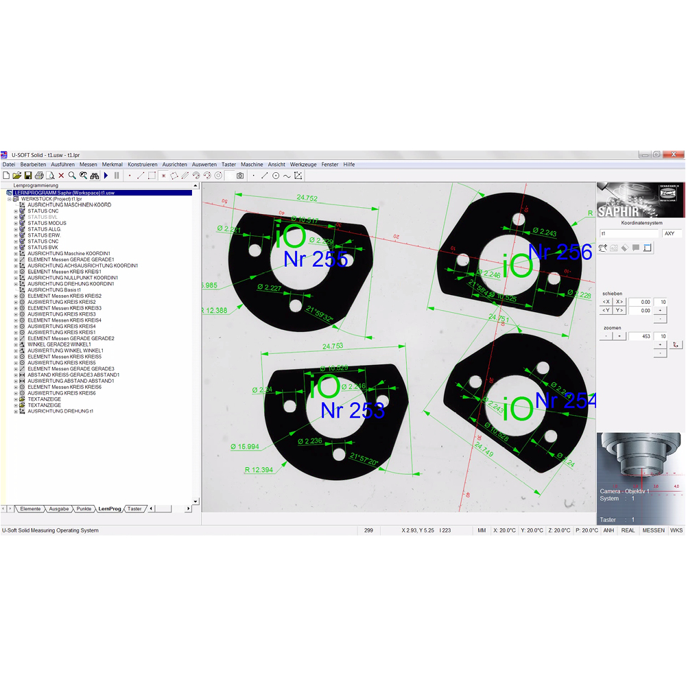
An innovation should start with the first action – not with the result. That is why SAPHIR QD measurement and analysis software can be intuitively operated and provides perfect measurement results with just a few clicks. Simply switch on the measurement device, load the object even without alignment or even the wrong way round – and detection and measurement can start. The report is displayed as an overlay on the live image together with a graphic report.
Multiple measurements – for all those who want everything at once
Whether multiple identical parts or multiple different parts: With the Multiple Measurement identical (MMI) and Multiple Measurement different (MMD), the developers at Schneider Messtechnik have now also integrated the option of multi-part measurement into SAPHIR QD. And the best of all: The software thinks with you. For this reason, the measurement elements can vary without additional intervention, the software scans all the parts in the measurement range. If a part is loaded for which a programme does not yet exist, the software nevertheless goes to work: Detect contour, create CAD drawing, carry out alignment – measure. In short: SAPHIR QD identifies all the elements to be measured and integrates these into the measuring programme at a click. Measurement technology can be that fast!
Special features of SAPHIR QD
-
Parts can even be loaded the wrong way round. The part is nevertheless recognised and the measurement performed.
- In addition to single-part measurement, the measurement of multiple identical parts at the same time is possible here (MMi=Multiple Measurement identical), as well as the simultaneous measurement of multiple non-identical parts (MMd=Multiple Measurement different).
- The software scans all the parts in the measurement range.No quantities have to be entered into the controller in advance.
- The contour is immediately detected, even if a part is loaded for which there is no existing program. The software aligns the workpiece automatically and saves the image from the measurement camera for part recognition.
- The measuring programme is automatically created as soon as the dimension arrows are moved to the relevant points of the DXF file.
- Alternatively, the software identifies all the elements to be measured independently with autodimensioning and integrates these automatically into the measuring programme.

SAPHIR QD
Brochures
